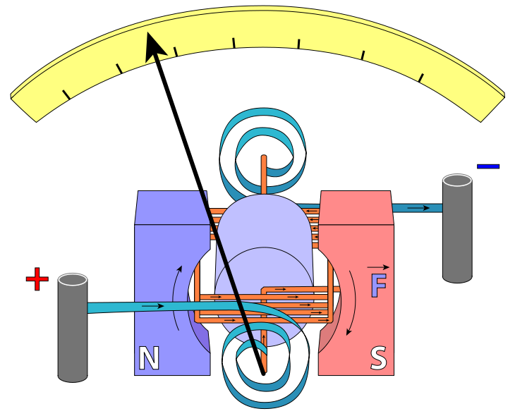

The coil is suspended so that it can rotate freely in the magnetic field. When a current flows, it enters the meter from the terminal connected to the spring, goes round the coil and returns back.
As the circuit is completed, the coil then rotates about the V-axis between the jewelled bearings.
The rotation is due to the two opposite forces of the current and the magnetic field.
This rotation is then opposed by the forces due to the springs. The pointer attains equilibrium position when the forces causing the rotation are equal to the forces due to the springs.
The angle of rotation is proportional to the current strength, that is, increase in current increases the angle of rotation.
The uniform scale is calibrated in a way that equal divisions represent equal changes in current. The value of the current can then be read on the scale.

Parts of an electric motor

When the armature is horizontal and current flows through the coil, the direction is clockwise. This produces S-pole on top of the armature, which then is attracted to the N-pole of the permanent magnet; likewise the N-pole of the armature at the bottom, which also gets attracted to the S-pole of the permanent magnet. Hence, the armature rotates through 90° about its axis to the vertical position.
As the armature rotates, the cummutator also rotates with it, making the split rings to interchange contact. This therefore reverses the polarity because the battery connection to the coil is reversed, thus, reversing the current’s direction.
This reversal in current produces N-pole in place of the S-pole. This created N-pole will now be repelled by the N-pole of the permanent magnet, making the armature to rotates another 90° about its axis to attains its horizontal position.
As the current continues to flow, the process is repeated, making the armature (coil) to rotate continuously.
EVALUATION (POST YOUR ANSWERS USING THE QUESTION BOX BELOW FOR EVALUATION AND DISCUSSION):
Read our disclaimer.
AD: Take Free online baptism course: Preachi.com 