It is a well known fact that energy menifests itself in different forms which are interconvertible into one another. Among different forms of energy, the electrical energy plays a very significant role in our daily life. Many chemical transformations and industrial processes are based on electrical energy and its relationship with chemical energy. There are large number of spontaneous redox reactions which form the basis of production of electrical energy. The device in which such chemical processes are carried out is called electrochemical cell or galvanic cell. For example, Daniell cell is based on the following redox reaction:
Cu2(aq) + Zn(s) à Cu(s) + Zn2+ + Electrical Energy
At the same time many of the non-spontaneous redox reactions can be made to occur by the use of electrical energy. Some examples are:
The branch of chemistry which deals with the study of relationship between electrical energy and chemical energy and interconversion of one form of energy into another is called electrochemistry. Electrochemistry is very vast and interdisciplinary branch of chemistry which finds tremendous applications. Its study is very important as it helps in the development of new technologies which are economical and environment-friendly. In this unit, we shall focus on the study of some aspects of electrochemical cells, batteries and fuel cells, etc.
Electrochemical Cells
Electrochemical Cells
The device in which chemical energy is converted into electrical energy is called galvanic cell or electrochemical cell or voltaic cell. In a galvanic cell, a redox reaction is carried out in an indirect manner and the decrease in free energy during the chemical process appears as electrical energy. An indirect redox reaction is such that reduction and oxidation processes are carried out in separate vessels. In order to understand this phenomenon, let us consider the redox reaction between Zn and CuSO4 solution.
Zn(s) + Cu2+(aq) à Zn2+(aq) + Cu(s)
The overall reaction is split up into two half reactions,
Zn (s) à Zn2+ (aq) and Cu2+ (aq) + 2e – à Cu(s)
Half Reactions and Redox Couples
The half reactions are used to form redox couples as described below.
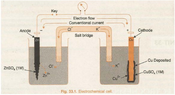
In its simple form, a zinc strip is dipped in the ZnSO4 solution and a copper strip is dipped in the CuSO4 solution taken in separate beakers. An arrangement involving contact between oxidised and reduced form of the substance such as Zn / Zn2+, or Cu/Cu2+ at the interface is called redox couple. The two metallic strips which act as electrodes are connected by the conducting wires through a voltmeter. The two solutions are joined by an inverted U-tube known as salt bridge. The U-tube is filled with the solution of some electrolyte such as KCl, KNO3 or NH4Cl to which gelatin or agar-agar has been added to convert it into semi-solid paste.
A schematic diagram of this cell has been shown in Fig. 33.1.
The deflection in voltmeter indicates that there is a potential difference between the two electrodes. It has been found that the conventional current flows through the outer circuit from copper to zinc strip. It implies that the electrons flow occurs from zinc to copper strip.
Let us now understand the working of the cell.
(i) Zinc undergoes oxidation to form zinc ions
Zn(s) à Zn2+(aq) + 2e – (oxidation)
(ii) The electrons liberated during oxidation are pushed through the connecting wires to copper strip.
(iii) Copper ions move towards copper strip, pick up the electrons, and get reduced to copper atoms which are deposited at the copper strip.
Cu2+(aq) + 2e – à Cu(s) (Reduction)
The overall cell reaction is combination of oxidation half and reduction half reactions.
Zn(s) + Cu2+ (aq) à Cu(s) + Zn2+ (aq)
The electrode at which oxidation occurs is anode and that at which reduction occurs is cathode. In the above cell, zinc strip is anode and the copper strip is cathode. Due to the oxidation process occurring at the anode it becomes a source of electrons and acquires a negative charge in the cell. Similarly, due to reduction process occurring at the cathode it acquires positive charge and becomes a receiver of the electrons. Thus, in the electrochemical cell, anode electrode acts as negative terminal and cathode electrode acts as positive terminal.
Salt Bridge and functions
Salt Bridge is a U-shaped tube containing a semi-solid paste of some inert electrolyte like KCl, KNO3, NH4Cl, etc., in agar-agar or gelatine. An inert electrolyte is one which:
(a) does not react chemically with the solution in either of the compartment.
(b) does not interfere with the net cell reaction. Function of Salt Bridge. In the electrochemical cell a salt bridge serves two very important functions :
(i) It allows the flow of current by completing the circuit.
(ii) It maintains electrical neutrality.
The transference of electrons from anode to cathode leads to a net positive charge around the anode due to increase in the concentration of cations and a net negative charge around the cathode due to excess of anions in solution. The positive charge around the anode will prevent electrons to flow out from it and the ·negative charge around the cathode will prevent the inflow of electrons at it. The reaction would thus, stop and no current will flow. The salt bridge comes to aid and restores the electroneutrality of the solutions in the two compartments. It contains a concentrated solution of an inert electrolyte the ions of which are not involved in electrochemical reactions. The anions of the electrolyte in the salt bridge migrate to the anode compartment and cations to the cathode compartment. Thus, the salt bridge prevents the accumulation of charges and maintains the flow of current. In the electrochemical cell, the salt bridge can be replaced by the porous partition which allows the migration of ions but does not allow mixing of the two solutions.
REPRESENTATION OF REDOX COUPLE AND GALVANIC CELL
Galvanic cell is a combination of two redox couples, namely; oxidation couple or oxidation half cell and reduction couple or reduction half cell. If M represents the symbol of the element and Mn+ represents its cation (i.e., its oxidised state) in solution, then
Oxidation half cell is represented as M / MD n+(c)
Reduction half cell is represented as MD n+(c)/M.
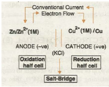
In both the notations c refers to the molar concentration of the ions in solution. Conventionally, a cell is represented by writing the cathode on the right hand side and anode on the left hand side. The two vertical lines are put between the two half cells which indicate salt bridge. Sometime the formula of the electrolyte used in the salt bridge is also written below the vertical lines.
For example, zinc-copper sulphate cell is represented as follows:
VARIOUS TYPES OF REDOX COUPLES OR ELECTRODES
Some important types of electrodes which are frequently used in electrochemical cells are described as follows:
- Metal-metal Ion Electrode. Such type of electrodes include a metal rod dipped in the solution of its own ions. Some examples are Zn/Zn2+ Ag/Ag+, .Cu/Cu2+ etc.
- Amalgam Electrodes. These are similar to metal-metal ion electrodes, but here the metal is used in the form of its amalgam with Hg. Amalgam is formed to modify the activity of metal. (Zn-Hg)/Zn2+ is one of the common example of this type.
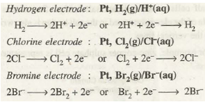
- Gas Electrodes. Such electrodes involve inert metal such as platinum dipped in the solution containing ions of the gaseous element. The arrangement is made in such a manner that gas and its ions are brought in contact at the surface of the inert metal. Some examples along with their electrode reactions are as follows:
Electrode Potential (E)
→ DEVELOPMENT OF ELECTRODE POTENTIAL
When a strip of metal (M) is brought in contact with the solution containing its own ions (M n+), then either of the following three possible processes can take place:
(i) The metal ion M n+ may collide with the metallic strip and bounce back without any change.
(ii) The metal ion M n+ may collide with the strip, gain n electrons and get converted into metal atom, i.e., the ion is reduced.
M n+ + ne – à M
(iii) The metal atom on the strip may lose n electrons and enter the solution as M n+ ion, i.e., metal is oxidised
M à M n+ + ne –
The above changes have been shown in Fig. 33.2.
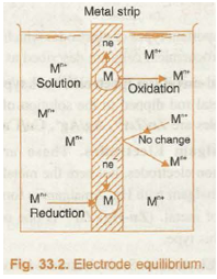
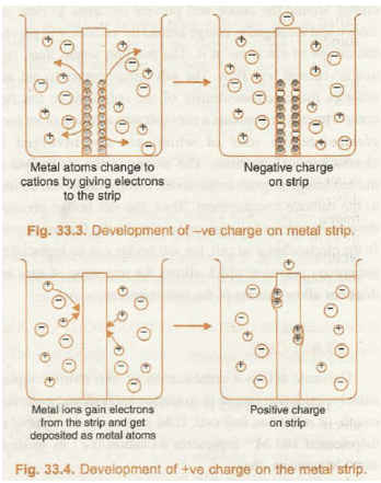
Now, if the metal has a relatively high tendency to get oxidised, its atoms would start losing electrons, change into positive ions and pass into the solution. The electrons lost, accumulate in the metal strip and cause it to develop negative charge. The negative charge developed on the strip does not allow metal atoms to continue losing electrons but it would reattract the metal ions from the solution in an attempt to neutralize its charge. Ultimately, a state of equilibrium will be established between the metal and its ions at the interface.

Similarly, if the metal ions have relatively greater tendency to get reduced, they will accept electrons at the strip from the metal atoms and consequently, a net positive charge is developed on the metal strip. Ultimately, a similar equilibrium is established between the metal ions and the metal atoms at the interface

The development of positive and negative charges on the metal strip has been shown in Fig. 33.3 and 33.4 respectively
Now, different metals have different tendencies to lose/gain electrons, therefore, they may develop different magnitude of negative or positive charge, which, unfortunately cannot be measured by any direct means. However, the separation of charges at the equilibrium state in either case, results in the electrical potential difference between the metal and the solution of its ions and is known as electrode potential.
The exact potential difference at the equilibrium depends on the nature of metal, its ions, the concentration of ions and the temperature.
According to the present IUPAC conventions, the half reactions are always written as reduction half reactions and their potentials are represented by reduction potentials. It may be noted that:
(i) Reduction potential (tendency to gain electrons) and oxidation potential (tendency to lose electrons) of an electrode are numerically equal but have opposite signs.
(ii) Reduction potential increases with the increase in the concentration of ions and decreases with the decrease in the concentration of the ions in solution.
STANDARD ELECTRODE POTENIAL (E)
The reduction potential of electrode when the concentration of the ions in solution is 1 mol L-1 and temperature is 298 K is called standard reduction potential (Ed) or simply standard electrode potential (E).
In case of gas electrode, the standard conditions chosen are 1 bar pressure and 298 K along with 1 M concentration of ions in solution.
The absolute value of E cannot be determined because once equilibrium is reached between the electrode and the solution in a half cell, no further displacement of charges can occur unless and until it is connected to another half cell with different electrode potential. This difficulty is overcome by finding the electrode potentials of various electrodes relative to some reference electrode whose electrode potential is arbitrarily fixed. The common reference electrode used forth is purpose is standard hydrogen electrode (SHE) whose electrode potential is arbitrarily taken to be zero.
Cell Potential or EMF of the Cell
→ Cell Potential or EMF of the Cell
The electrochemical cell consists of two half cells. The electrodes in these half cells have different electrode potentials. When the circuit is completed the loss of electrons occurs at the electrode having lower reduction potential whereas the gain of electrons occurs at the electrode with higher reduction potential. The difference in the electrode potentials of the two electrodes of the cell is termed as electromotive force (abbreviated as EMF) or cell voltage (E cell). Mathematically, it can be expressed as
EMF = E red (Cathode)- E red (Anode) or simply as
E cell = E cathode – E anode
Since in the representation of a cell, the cathode is written on right hand side and the anode on left hand side, therefore, EMF of a cell is also sometimes written as: ·
EMF = E Right – E Left = ER – E1
EMF of the cell may be defined as the potential difference between the two terminals of the cell when either no current is drawn from it. It is measured with the help of potentiometer or vacuum tube voltmeter.
The EMF of the cell depends on nature of the reactants, concentration of the solutions in the two half cells, and the temperature. The EMF of the cell at the standard state conditions is called standard EMF and can be calculated from the standard electrode potentials of the two half cells.
E cell = E cathode – E code
Standard Hydrogen Electrode (SHE)
→ Standard Hydrogen Electrode (SHE)
Standard hydrogen electrode (Fig. 33.5) consists of a platinum wire sealed into a glass tube and carrying a platinum foil at one end. The platinum foil is coated with finely divided platinum. The electrode is placed in beaker containing an aqueous solution of some acid having one molar concentration of H+ ions. Hydrogen gas at 1 bar or 100 kPa pressure is continuously bubbled through the solution at a temperature of 298 K. The oxidation or reduction in the SHE takes place at platinum foil. Hence, it can act as anode as well as cathode and may be represented as:

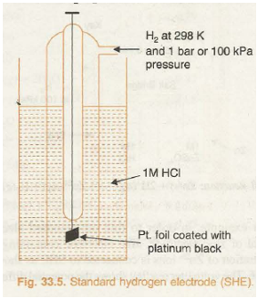
If SHE acts as anode then oxidation will take place at it as

If SHE acts as cathode then reduction will take place at it as

Measurement of Standard Electrode Potentials
→ Measurement of Standard Electrode Potentials
In order to determine the standard electrode potential of an electrode, the electrode in standard conditions is connected to standard hydrogen electrode (SHE) to constitute a cell. If the electrode forms the negative terminal of the cell it is allotted negative value of electrode potential and if it forms the positive terminal of the cell, it is allotted a positive value of electrode potential. The potential difference between the electrodes is determined with the help of potentiometer or vacuum tube voltmeter. At the same time, the direction of flow of conventional current in the external circuit is also noticed with the help of galvanometer. This helps us to know the positive and negative terminals of the cell because conventional current in the external circuit flows from +ve terminal to -ve terminal. Now, the direction of the flow of electrons is opposite to that of conventional current. Since electron flow in external circuit occurs from anode to cathode it helps us to mark anode and cathode electrodes of the cell.

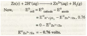
Knowing the E cell and electrode potential of one of the electrodes (SHE), that of the other can be calculated
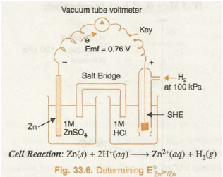
For example, in order to find out standard electrode potential of zinc electrode, zinc electrode containing 1 M concentration of Zn2+ ions is connected to SHE as shown in Fig. 33.6. The voltmeter reading shows the potential difference of 0.76 volts. The electron flow is found to be from zinc electrode to SHE. From this it follows that Zn acts as anode while SHE acts as cathode. The net cell reaction is
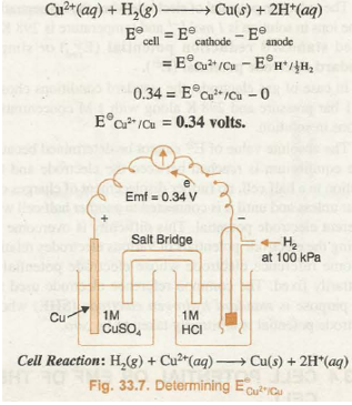
Similarly, when standard copper electrode is coupled with SHE the voltmeter reading shows a potential difference (E cell) of 0.34 volts. The electron flow is found to occur from SHE towards copper electrode as shown in Fig. 33.7. Therefore, SHE in this cell acts as anode and copper electrode acts as cathode. The cell reaction is
Electrochemical Series
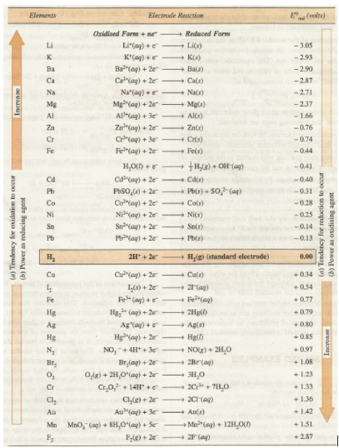
We have seen that different metal/metal ion combinations have different values of standard electrode potentials. The various elements can be arranged in order of increasing or decreasing values of their standard reduction potentials. The arrangement of various elements in the order of increasing values of standard reduction potentials is called electrochemical series. The electrochemical series, also called activity series consisting of some electrodes along with their respective reduction reactions has been given in Table 33.1.
Table 33.1. Standard Electrode Potentials
EVALUATION
W hat is the voltage of the cell represented as Zn(s)/Zn2+(aq)//Cu2+(aq)/Cu(s)?
Given that Cu2+(aq)/Cu(s) E0=+0.337V
Zn(s)/Zn2+(aq) E0=0.763V
Read our disclaimer.
AD: Take Free online baptism course: Preachi.com 