CONTENT
- Moving a Conductor within a Magnetic Field
- A/C and DC Generator
- Transformer
- Power Transmission
MOVING A CONDUCTOR WITHIN A MAGNETIC FIELD
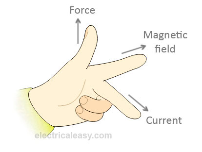
Induced current can also be produced by moving a conductor in a magnetic field. The direction of such current can always be obtained by applying the Fleming’s Right hand rule which states that “If the thumb, forefinger and middle finger are held mutually at right angles to one another with the fore-finger pointing in the direction of magnetic field, the thumb pointing in the direction of Motion (of the conductor), then the second finger will point in the direction of the induced Current.”
A.C AND D.C GENERATOR
A machine that converts mechanical energy into electrical energy or electrical energy into mechanical energy is called a dynamo. When it changes mechanical energy into electrical energy it is called a generator, but when it changes electrical energy into mechanical energy, it is called a motor.
There are two classes of generators, the alternating current (A.C) generator and the direct current (D.C) generator.
The A.C. generator consists of:
- an armature – a rectangular coil consisting of a large number of turns of insulated wire wound on a laminated soft iron core.
- a magnetic field created by the curved poles of a horse-shoe magnet or an electromagnet.
- two copper slip rings to which the ends of the rectangular coil are connected and which rotate with the armature.
- two stationary carbon brushes which are made to pressed lightly against the slip rings

EVALUATION
- Draw a labeled diagram of A.C generator
- Describe the principle of operation of A.C generator.
DIRECT CURRENT (D.C) GENERATOR
An A.C generator can be made to produce a D.C by replacing the two slip rings with a single split ring or commutator. A split ring commutator is a split ring that has been split into two segments which are insulated from each other. The ends of the coil are connected one to each split ring or commutator segment.
The commutator is a current reverser. When the armature coil is rotated, the commutator automatically switches each end of the coil from one brush to the other each time the coil completes one-half of a revolution. As the current reverses in the coil after each half revolution, the connection between the coil and the brushes are reversed through the action of the commutator.
TRANSFORMER
A transformer is an electrical device for changing the size of an a.c. voltage. It acts to increase or decrease the em.f of an alternating current. It consists of two separate sets of coil, the primary coil and the secondary coil. The primary coil is the input winding of turns of wire and the secondary coil is the output winding. The coils are wound round a soft-iron core. The soft-iron core acts to increase and concentrate the magnetic flux within the core. It is also laminated, i.e. it consists of sheets of soft-iron insulated from each other instead of a solid block of iron. This lamination reduces loss of energy in the form of heat due to eddy currents introduced in the core.

STEP DOWN TRANSFORMER
When an alternating e.m.f. or A.C voltage (EP) is applied at the terminals of the primary coil (p), an alternating magnetic flux is produced in the iron core which links or threads the secondary coil (s). An alternating e.m.f (Es) of the same frequency as that Ep is induced in the secondary coil by mutual inductance.
Mutual inductance is the flow of induced current or voltage in a coil due to an alternating or varying current in a neighboring coil.
The total flux linking the two coils is proportional to their number of turns. The induced e.m.f in the secondary coil (Ep) depends on the e.m.f. in the primary coil and on the ratio of the number of turns in each
:. ES= Ns
EpNp
In an ideal transformer with a 100% efficiency, the power developed in the secondary coil is equal to the power developed in the primary coil.
:. Es= Ip
Ep Is
Hence,Es = Ns= Ip
EpNpIs
To use a transformer to increase an applied voltage, i.e to make Es greater than Ep, Ns must be greater than Np. Such a transformer which increases or steps up the applied or primary voltage is called a step-up transformer. In a step-up, the primary current is greater than the secondary current but the primary voltage is less than the secondary voltage.
ENERGY LOSSES IN PRACTICAL TRANSFORMER
There are energy losses in practical transformers due to:
- Eddy currents
- Hysteresis loss
- Heat loss
- Leakage of magnetic flux
Eddy Current reduces efficiency because they consume power and this causes energy lost in the form of heat. Such loss can be reduced by laminating the core.
Hysteresis loss is wasted energy due to reversing the magnetization of the core. It is reduced by the use of special alloys in the core of the primary coil.
Heat loss is the primary and secondary coils have resistance, some energy is lost in the form of heat (I2R) in the coils. This can be reduced by using thick wires or low resistance coils.
Some energy is lost due to leakage of magnetic flux. This arises because not all the lines of induction due to current in the primary coil pass entirely through the iron core. This loss is reduced by efficient core design.
Examples
1. Find the turns ration in a transformer which delivers a voltage of 120V in the secondary coil from a primary voltage of 60v.
Turns ration =Ns= 120= 2
Np60
2. Atransformer has 500 turns in the primary coil and 300 turns in the secondary coil. If the primary coil is connected to a 220v mains, what voltage will be obtained from the secondary coil? What type of transformer is this?
Es = Ns
EpNp
Es =300
220 500
Es = 220 x 300
500
Es = 132 V
It is a step-down transformer because secondary voltage is less than primary voltage (132 < 220)
3. A transformer supplies 15v from a 220v mains. If the transformer takes 0.7A from the mains when used to light three lamps connected in parallel and each rated 15v, 40w calculate:
i. the efficiency of the transformer
ii.the cost of using it for 24hrs at 30k per kwh.
Primary or input power = IpVp
= 0.7 x 220 = 154w
Secondary (output power) =IsVs = (Is x 15 )W
p = ISV
p = Is
V
Is = 40= 2.67A.
15
Total current taken by the 3 lamps in parallel = 3 x 2.67 =8A
:. Output power = 8 x 15 = 120 W
Efficiency = Output Power X 100
Input Power
= 120x 100 = 78%
Power consumed = 0.7 x 220Kw
1000
Total power consumed in 24 hrs
= 0.7 x 220 x 24kwh
1000
Cost at 30k per Kwh
= 0.7 x 220 X 24 X 30
1000 100
= N1
EVALUATION
- Draw a labeled diagram to explain the working of a transformer which can produce 24v from a 240v supply.
- Give two reasons which explain why the efficiency of the transformer cannot be 100%.
POWER TRANSMISSION
Power generated at power stations are distributed over large distances to consumers through metal cables. Power can be transmitted either at low current and high voltage or at high current and low voltage. Because the metal cables through which the power is transmitted have a certain amount of electrical resistance, transmitting power at high current will lead to loss of energy in the form of heat. To avoid this, power is transmitted at high voltage and low current. This is known as high tension transmission.
Low currents leads to low energy loss. It also requires thinner cables, cost of cable materials is considerably reduced if power is transmitted with low current and high voltages.
Step down transformers are used to reduce the high transmitted voltages to lower voltages required in home and factories.
READING ASSIGNMENT
New School Physics for Senior Secondary Schools (M.W. ANYAKOHA Pages 447 – 457).
GENERAL EVALUATION
- A block of mass 2.0Kg resting on a smooth horizontal plane is acted upon simultaneously by two forces, 10N due north and 10N due east. The magnitude of the acceleration produced by the forces on the block is.
- Two forces 3N and 4N act on a body due north and due east respectively. Calculate the equilibrant.
WEEKEND ASSIGNMENT
- Which of the following is not a part of an a.c generator? (a)carbon brushes (b)slip rings (c) communicator (d) field magnets
- To convert an alternating current dynamo into a direct current dynamo the(a) number of turns in the coil is increased (b) strength of the field magnet is increased (c) slip rings are replaced with split ring commutator (d) coils is wound on a soft iron armature
- The current in the primary coil of a transformer is 2.5A, if the coil has 50turns and the secondary 250 turns calculate the current in the secondary coil. (a)0.2A (b) 0.5A (c)2.5A (d)5.0A
- A voltage of 240V is connected to the primary coil of a transformer. Calculate the ratio of the primary turns to the secondary turns if the voltage available at the secondary coil is 15V (a) 0.06 (b) 0.90 (c) 1.16 (d) 16.00
- An inductor of inductance 10H carries a current of 0.2A. Calculate the energy stored in the inductor. (a)0.11J (b) 0.20J (c) 1.10J (d) 2.00J
THEORY
- State three ways by which energy is lost in a transformer and how it can be minimized.
- State the laws of electromagnetic induction.
- Distinguish between a step-up and a step down transformer.
- State three methods by which by which high e.m.f can be obtained from a generator.
Read our disclaimer.
AD: Take Free online baptism course: Preachi.com 
Free Science simulations at Classadapt (UK) Classadapt.com