Survey is an applied science which has mathematical orientation in examining and making careful measurement. Various surveying methods are normally used for two distinct purposes.
- To determine the relative positions of points, natural or artificial features of the earth, so that they may be correctly represented on maps
- To set out on the ground the position of construction or engineering works.
BRANCHES OF SURVEY
Survey may be classified based on:
- The purpose
- The technique or equipment to be used
THE PURPOSE: The branches of survey identified based on their principal purposes are
GEODICTIC SURVEYS: These are high accuracy surveys concerned with the shape of the earth or position, fixing of points which provides control for lower accuracy survey
TOPOGRAPHICAL SURVEYS: These are survey works based on the location of the main artificial or natural features of the earth including hills, valleys, well, villages, towns, railways lines etc.
CADASTRAL SURVEYS: These are survey works based on the preparation of plans, showing and defining the legal property boundaries
ENGINEERING SURVEY: These are the preparatory aspects of engineering works to its execution. The common types are roads rails dams, channels and other types construction works
OTHERS: The several other types that can be identified are Geographical Survey, Geological Survey and Military Survey.
THE PRINCIPAL TECHNIQUES FOR SURVEYING
The principles techniques used for survey include
- Chain surveying
- Traverse surveying
- Hydrographic surveying
- Triangulation surveying
- Plane table surveying
- Aerial surveying
THE FUNDAMENTAL PRINCIPLES OF SURVEYING
Since surveying concerns measurement, its practise necessarily requires the knowledge of mathematics, especially in the area of Algebra, Plane Geometry, Trigonometry and most importunity. Plane – table surveying. Another important point to the note is surveying is that for limited point to the note in surveying is that for limited areas, ordinary theory of plane geometry is sufficient to carry out its operations.
CHAIN SURVEYING
This is the simplest and oldest form of land surveying and is still extensively in use. It is based on the principles that if a triangle is set out upon the ground and the lengths of the sides measured. It may later be plotted in the drawing office to any desired scale. The only instruments required are a pair of compasses and a scale rule.
THE INSTRUMENTS USED IN CHAIN SURVEYING
- THE CHAIN: The chain is usually made of steel wire and consists of long links joined by short links. It is designed for hand usage and is sufficiently accurate for measuring the chain lines and offsets of small surveys.
The chain consists of one hundred long links each ten links beings marked by a brass tally. To avoid confusing in reading, chains are marked similarly form both ends. i.e. the tally for 2m and 18m is the same, so that measurement may be commenced with either end of the chain.
- STEEL BAND: Steel band may be 30m, 50m or 100m long, and 133mm wide. It has handles similar to the chain and is wound on a steel cross. It is more accurate but robust than the chain
- TAPES: Tapes are used where greater accuracy of measurement is required, such as the setting out of buildings and roads. They are marked in metres, centimeters and millimeters. They are usually 15 or 30m long, and are of three types.
- Linen with steel wire woven into the fabric: These tapes are prone to being stretched in use and should be frequently tested for lengths. They should never be used at work for which great accuracy is required
- Fiberglass: These are much stronger than linen and will not stretch in use.
- Steel tapes: These are much more accurate and are usually used for setting out building and always used for setting out structures
- ARROWS: Arrows consist of pieces of steel wires about 0.5m long and are used for making temporary stations. A piece of coloured cloth is usually tied to the end of the arrow to make it more conspicuous in tall grasses.
- STATION PEGS: Station pegs are made of wood and are usually 50mm x 50mm long. They are used to mark the stations
- RANGING POLES: These are made of wood or tabular steel and are usually 2m long. They are painted in alternate bands of red, and white, the bands generally being 0.5m deep so that the pole may be used for measuring offsets.
- CROSS STAFF: This instrument is used for setting out liens at right angles to the man chain line. It consists of two pairs of vanes set at right angles to each other with a wide and a narrow slit in each vane. The instrument is mounted upon a pole, so that it will be at the eye-level.
- OPTICAL SQUARE: This instrument is used for similar purpose like the cross staff, but it’s easier to use and of greater accuracy.
- The mirror method: Its construction is based on the fact that a ray of light is reflected from a mirror at the same angle as t hat at which it strikes the mirror.
- The prism square method: This is a simplified form of optical square consisting of a single prism. The staff is then observed through a peep – hole above the prism. No adjustment can be made to this instrument, the surveyor has to rely on the accuracy of the prism.
- WATKIN’S CLINOMETER: This instrument is used for measuring the angles of ground slopes. There are several forms, but all are basically the same a common form is the Watkin’s clinometers, which consists of a counter weighted scale freely suspended so that the line OX is always horizontal. The scale is divided from 0 in both elevation and depression.
To measure the ground slope from a line AB, using the Watkin’s Clinometer, the surveyor stands at A, while an assistant stand at B with a pole clearly marked at a point at the eye-level of t he surveyor. This point is observed through the instrument at A, and if it is at a higher level then A, the instrument will be upwards. As, however the scale is freely suspended, its position in relation to the Horizontal level will not later and the angel of elevation may be read upon the scale from a fixed mark on the clinometers case.
- FIELD BOOK: The field book is about 100mm x 200mm and opens length –wise, the pages being ruled as seen below. When using this the entries are commenced at the back and continued towards the front. Thus the surveyor record measurements forward in the same direction as that in which he is walking. Always commence by inserting the date and place of survey, together with the name of the person making it. This should be followed by a diagrammatic sketch of the chain lines, the station being lettered, and the number of the line and direction in which it is to be measured.
When entering details, of the survey, the following should be noted:
- Features such as hedges are sketched in the book
- No features are drawn across the pair of lines, being used for dimension
- Where other survey line intersect the line being measured, their direction are indicated
- The distant of hedges from the main chain lines are inserted beside the dimension on the line form which the offset was taken.
PROCEDURE FOR MAKING A CHAIN SURVEY
- Walk over the area to be surveyed, and not the general layout, the position of features and the shape of the area
- Decide upon the frame work to be used and drive in the station pegs.
- Sketch the layout on the last page of the chain book, together with the date and the name of the surveyor. The longest line of the survey is usually taken as the base line and is measured first.
SLOPING SITES
In some cases, the angle of slope of the ground between two stations is such that the length of the line measured on the slope is appreciable greater than the horizontal distance between the stations. As the horizontal distance is required for plotting the survey, any slope greater than 3 should be adjusted in one of the following ways:
- Stepping the Chain: Short lengths of chain are held horizontally and plumbed down to the ground surface, the action being repeated until the second station is reached.
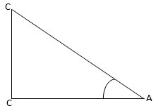
- Measure the angle of slope by means of clinometer and calculate the horizontal length of the line of trigonometry (see the above diagram) AB = AC cos a
CIRCUMVENTING OBSTACLES
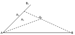
- TO RNAGE A LINE OVER A HILL BETWEEN TWO STATIONS NOT VISIBLE FROM EACH OTHER
Set up poles at stations A and B. an assistant with a ranging pole is stationed at B1 approximately on the line AB and form where he can just see the pole at A. The surveyor with a further pole walks from A towards B1, until he can see B. he is then lined in-between A and B1 by the assistant, and places his pole at A. The assistant is then lined in-between A1 and B by the surveyor, his position now being at B2 where he can see A. The surveyor is then lined in by his assistant to position A2, on the line B2A, where he can see B. This process is continued until all poles are in a straight line.
- SETTING OUT A RIGHT ANGLE FROM A CHAIN LINE BY THE 3, 4, 5 METHOD
This is based o n the fact that a triangle having sides whose lengths are in ratio of 3, 4, 5 is a right-angle triangle. The procedure is as follows.
To set up a line AB at point A on line XY and at right angle to XY, measured back towards X a distance of 9m to point C, then with the end of the tape held at A and 27m point held at C, hold
- TO MEASURE A LINE ACROSS A POND
To measure the distant BC, range AB through C. line through B to any convenient place at point D which clears the pond.
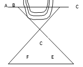
With a point at D, range in E making DE – BD. Produced CD to F so that DF = CD, then by identical triangle FE = BC
- TO MEASURE THE LENGTH OF A LAKE
A frame work of liens is set out round the area, the corners being triangulated. This method is not very accurate, but often proves useful. It is known as chain traversing.
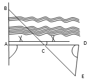
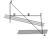
- TO MEAUSRE THE LENGTH OF A CHAIN LINE CROSSING A RIVER
- At right angles: Set up poles at A and B. Set out AD at right angles to the chain line. Set up a pole at C so that AC = CD. Set out DE at right angle to AD, and locate E so that ECB is one triangle lien. Then ABC and CDE are identical triangles and AB = DE
Obliquely: Set up poles at A and B. locate C so that BCA is a right angle (by optical square). Continue on CB to D so that DB = BC. Erect DE perpendicular to DC. Then triangle BDE = Triangle BCA and AB = BE
TRAVERSE SURVEYING
A traverse is a continuous framework of lines connecting a number of points, the lengths of the lines and their angular relationship to each other being measured. The lines are known as legs and the points as stations.
TYPES
- CLOSED TRAVERSE: When the framework forms a closed figure or when the traverse connects two stations whose positions are known, it is known as a closed traverse. This type of traverse is used for surveying woods, lakes, building block, etc.
- OPEN TRAVERSE: This is a traverse whose starting points and stations do not coincide or or are not both fixed. This type of traverse is used to survey rivers, roads or railway routes. To enable the work to be checked, sights are taken on to some reference objects such as a church tower, factory chimney or other well-defined landmark.
USES
Traverse surveys are used where site conditions make the chain triangulation method impossible, i.e. a wood, build-up factory block, long-winding river or where the survey is of a larger area and details are not required.
METHOD OF TRAVERSE SURVEYING
The three principal method of traverse surveying are:
- Chain and compass
- Theodolite
- Chain
COMPASS TRAVERSE: The prismatic compass always points towards magnetic north, so that when making a compass traverse the angles of the legs are related to a north-south line or meridian

Bearing: This term bearing refers to the angle between the line and the north-south meridian.
- THEODOLITE TRAVERSE: This is essentially a telescope whose line of collimation may revolve through 360 horizontally and transited (i.e. revolve) through 360 vertically and the angles of revolution measured
USE
Theodolite traverse method is often used where high degree of accuracy is required
- CHAIN TRAVERSE: This refers to framework of lines set out around the area, the comers being triangulated. Although the method is not very accurate. It often proves useful.
ASPECTS OF ENVIROMENTAL INTERACTION
PERFORMANCE OBJECTIVES
At the end of this chapter, students should be able to:
- Identify the components of the land ecosystem and describe their relationship
- Explain the relationships and interdependencies among the components;
- Describe the nature of balance in hydrological cycle using appropriate environmental variables;
- Explain how any change in the components of ecosystem can affect its balance.
DEFINITION OF ENVIROMENT
Environment is defined as the total surrounding or medium of any organism in a given area. This includes the physical surroundings, climatic factors and other living organism in that surrounding.
Spheres of the Environment
The environment, which is the earth, is grouped into four spheres and these are:
- Lithosphere: This is the solid portion of the environment which contains rocks, sand, soil mineral, etc.
- Hydrosphere: This is the liquid part of the environment like rivers, lakes and ocean
- Atmosphere: This is the gaseous portion of the environment where gases like oxygen,, nitrogen and carbon dioxide are found.
- Biosphere: This is the portion of the environment where plants and animals are found. The four spheres of the environment are interrelated and interdependent on each other.
Read our disclaimer.
AD: Take Free online baptism course: Preachi.com 
Free Science simulations at Classadapt (UK) Classadapt.com